


Service
FAQs
This page contains key information about the different products, plus guides and descriptions. We also provide useful troubleshooting tips so you can identify issues and fix them yourself. In many cases, a small tweak can have a big impact on the functioning of the machine. If you can’t resolve the issue on your own, we advise that you contact an authorised repair shop.
Choose your topic
Pressure
Useful information about pressure
The pressure and nozzle size determine the amount of pesticide that is applied. The pressure is influenced by the vehicle speed (drive shaft speed) and the number of open nozzles. Please see the recommendations for the ideal pressure range provided by the nozzle manufacturer or by the Julius Kühn Institute.
You can calculate the required operating pressure using the following equation:
Ltr./Ha x Row width x Speed / 600 / No. open nozzles =
(Note: multiply the result by two if implementing two-row application)
Example:
400 Ltr./Ha x 1.80m x 6.5 km/h / 600 / 12 nozzles = 0.65 Ltr./min
(Equivalent to 10 bar with ATR-brown or 8 bar with CVI-orange)
Multiplied by 2 = 1.3 Ltr./min for two-row application
(Equivalent to 9 bar with ATR-orange or 8 bar with CVI-yellow)
Pulsating pressure
Pulsating pressure is when the pressure gauge is oscillating around one bar of pressure. This is generally due to the pump rather than the valve. Fluctuations in pressure below one bar of pressure can be caused by small deposits or dirt. They can often be ignored as the issue will simply disappear after a short period. If not, please check the following:
- Check the pump air reservoir (5-8 bar). Make sure that the air doesn't escape when depressed (only for membrane pumps)!
- Check that the pump cable is sealed (external air is suctioned)
- Check that the pump cable is not blocked (pump doesn't receive enough liquid)
- Clean the suction filter and gasket
- Clean the pressure filter
- Check the pump valves for dirt and/or wear and tear
- Replace the pressure gauge
- Open the front cover on the pump and replace the gaskets (membrane pump)
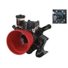
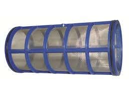
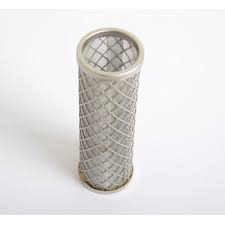
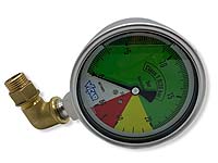 Pump Suction filter Pressure filter Pressure gauge
Machine doesn’t build up any pressure
Check the return flow on the control valve in the container
- If there is no water, the problem is with the pump
- If there is water, the problem is due to escaping pressure
For 1:
The pump valves may stick after a long period of downtime. This prevents the pump from drawing in air so that no pressure can be established. Ensure that the pressure is dissipated prior to every use, so the pressure gauge does not become damaged in the case of a sudden build-up of pressure! You can loosen the valves by taking the following steps:
- When the machine is operating, abruptly open and close the free ball valve on the valve several times. This creates backcoupling to the pump and helps to loosen the valves.
- The domestic water connection can be used to spray water under full pressure into the pump’s suction pipe to loosen the valves.
- The valves must be removed and cleaned.
For 2:
A loss of pressure can be caused by:
- Open drum cleaning nozzle (close the ball valve)
- Open flushing mechanism (close the ball valve)
- Cracked agitator nozzle (replace)
If the problem still hasn’t been resolved, check the following:
- If the valve bolt is getting stuck in the regulating valve, clean or replace it
- Check that the pressure motor is working correctly
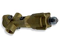
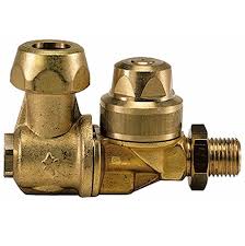
Pressure changes when opening and closing the section valves (nozzles)
Opening and closing the section valves changes the position of the valve spool in the regulating valve. If one or more section valves are closed, the spool opens to allow more liquid back into the pesticide container. If this valve spool sticks, it cannot return to its original position, thus affecting the pressure of the system.
- Check the regulating valve and clean it or replace any worn parts
Regulating valve
Loss of pressure (insufficient pressure built up)
- Slowly close the flushing nozzle container
- Slowly close the flushing mechanism
- Check the agitator nozzle for hairline cracks / to see if it is broken
- Check the regulating valve
- Check the electric pressure motor
Flushing nozzle Flushing mechanism Agitator nozzle Pressure motor
Pressure drops at a certain capacity
The pump is receiving too little liquid. A vortex can often form in the liquid container.
- Check the pipe isn’t blocked or narrowed (ball valve).
- Remove any foreign bodies from the pump’s suction duct
Nozzle calculator
Tank
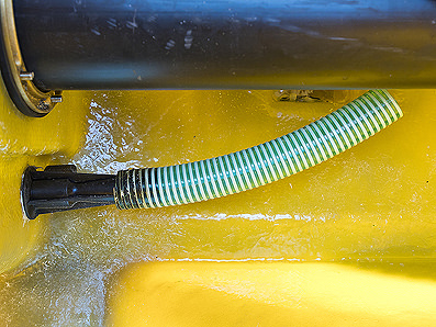
Useful information about the agitator nozzle
The agitator nozzle is located at the front left in the direction of travel. A second agitator nozzle is installed diagonally opposite (rear right) for capacities of over 1,500 litres. These injector agitator nozzles are pressure-controlled. The higher the pressure, the stronger the agitation. The pipe located above serves to reduce the formation of foam and can be either shortened or removed altogether. You can also use an anti-foaming agent (available for distilleries) to prevent the formation of foam.
Agitator nozzle
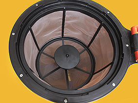
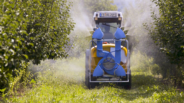
Useful information about the flushing nozzle
The flushing nozzle or cleaning nozzle sits below the filling sieve on attachments over 500 litres, or on the drum duct for trailers. These nozzles are not mounted on ball bearings – as such they must only be used to briefly clean the pesticide tank and not for agitation! As the throughflow is very high, when the flushing nozzle is open, the pressure completely dissipates. Make sure you close the nozzles immediately after cleaning to prevent damage!
Flushing nozzle
Pesticide from the pesticide tank leaks into the rinsing tank
- The three-way valve is not sealed tightly. Gently tighten the union nut or replace it (attachments)
- The ball valve used to open the rinsing container is not sealed – replace it (trailer)
- The pesticide tank is not sealed off from the rinsing tank (trailer)
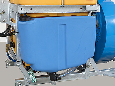
Rinsing tank
Nozzles
Useful information about the jet nozzle
Useful information about the jet nozzle The jet nozzle links the sprayer and the pesticide. It is responsible for dosing, droplet formation, the amount of pressure and the drift. Key factors to consider when choosing the type and size of the jet nozzle include the application rate, the row width, the vehicle speed and the number of nozzles. We recommend consulting the nozzle manufacturer or the Julius Kühn Institute.
Nozzles don't stop spraying
- Check the section valve (magnetic valve) is sealed correctly (loosen the hoses)
- Check the high-pressure hoses leading to the nozzles (replace if required)
- Check the drip stop membrane is clean and undamaged
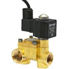
Magnetic valve Nozzle
No output from the nozzle(s)
- The inner gasket of the nozzle is worn (replace the gasket / nozzle body)
- The nozzle pipe is blocked or damaged
- The electric magnetic valves are not switching (check the electronics and clean the valves)
Nozzle Magnetic valve
Nozzle calculator
Electrics
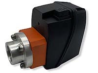
Pressure motor not responding
- Check the power
- Check the pressure motor
- Check the pressure motor drive
Pressure motor
Magnetic valves not switching
- Check the power diode
- Check / clean the stator (use sandpaper to clean around the piston and its sleeve)
- Clean the diaphragm on the red rubber ring, checking for cracks.
Magnetic valve
Fan
Useful information about the fan
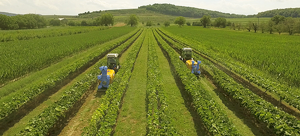
The liquid is transported by air. The airflow plays a decisive role in dictating the range and drop placement. It also massively impacts the direction of flight and the drift. The amount of power required depends on the operating speed, row width and foliage density. The greater the power of the fan, the slower the motor can operate and the less fuel is required. Caution! The engine power can be too low on steep slopes!
Useful information about setting the air outlets (general information)
It is important that you always integrate all of the air outlets, even if not all nozzles are required!
Combining several airflows stabilises and increases the penetration. For example, you can bundle all of the air outlets to one side to achieve greater range.
In the case of radial blowers with rotating air outlets, the lowest and uppermost nozzles confine the pesticide to the foliage area to create as little drift as possible. If present, the central air outlets are centred.
Useful information about setting the air outlets (viniculture)
It is important that you always integrate all of the air outlets, even if not all nozzles are required!
In viniculture, all of the air outlets on one side can be centred to point at a specific area, for example to spray shoots or for special grape treatment. Combining several airflows stabilises and increases the penetration. This not only reduces the drift, but also leads to savings in terms of speed and, therefore, fuel consumption. Depending on the desired application quantities, you can then use one, two, three or more nozzles.
In the case of a full canopy/full foliage, the upper and lower nozzles demarcate the canopy to keep the amount of drift to a minimum. For models 456 and 460, the central air outlet is centred to ensure an even distribution.
For an increased adsorption in the grape zone or to treat peronospora on the shoot tips, the central outlet is directed at the area to be treated without creating a spray shadow. This makes it possible to control the overlapping and to apply different amounts to the canopy/foliage without needing to use different sized nozzles. ► Settings diagram

Selecting the correct gear
- As a general rule of thumb, second gear reduces power and fuel consumption. First gear is for slow tractors or to generate a higher RPM on steep slopes.
No air flow
- Check the gear
- Clean the blades in the base of the casing (behind the air outlet)
- Check the butterfly valves
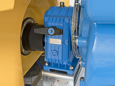
Gear Butterfly valves
Gearbox getting hot
Layer of grease by the air outlet
Imbalance noises on the turbine
Radial blowers achieving very high speeds. This can lead to noises caused by wear e.g. on a ball bearing, the shaft, the pump or the tractor transmission. If these noises are only noticeable at a specific speed range, they could be due to the change of load affecting the tractor transmission (i.e. not a sign of damage!) The noise should disappear when the speed changes.
Pump
Pump pulsating
- Check the pump air reservoir (membrane pump 5-8 bar)
- Check the pump pipe is sealed
- Check the pump pipe isn’t blocked
- Clean the suction filter
- Clean the pressure filter
Pump Suction filter Pressure filter
Air reservoir does not maintain pressure (membrane pump)
Pump leaks oil
Pump forces oil out of the oil container (membrane pump)
Screws are loose or broken
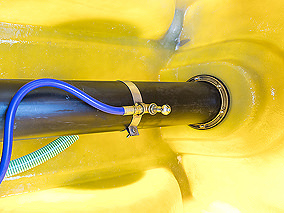
Screws come loose for no reason – this is mostly due to vibration and pressure!
If the screws in the pump bracket come loose, it is generally due to the pressure from the drive shaft. If the shaft is too long, or the sectional tubes have become damaged, pressure is exerted on the pump every time you steer. Steering the tractor causes the sectional tubes to plunge into the drive shaft. Traction from the blower causes the external pipe to wedge against the internal pipe causing friction. (Insufficient lubrication accelerates this process). The outcome: the screws between the frame and the pump come loose. Sometimes these even break off, causing additional damage to the drum duct. The strength of the tractor places a key role in this wear and tear.
You should check the following things regularly:
- Ensure that the drive shaft has a distance of at least 20cm on trailers and at least 5cm on attachments from the plunge (note when changing the tractor).
- Regularly check the sectional tubes for friction. Take apart the shaft and carefully check there are no sharp edges on the inner pipe (risk of cutting). Warning: Don’t confuse the anti-friction finish with sharp edges.
Drawbar
All you need to know about the drawbar
The drawbar is responsible for accurately tracking the machine. This can be set individually for different tractors using the so-called pendular compensation. The lower link pins can be pushed in or out for this purpose. The distance from the drawbar fulcrum to the tractor’s rear axle and the axle on the sprayer are decisive for accurate tracking.
To check the tracking, proceed as follows:
- Line up the tractor and sprayer (attached)
- Now lay a flat, blunt object (e.g. a stone) centrally near the tractor’s rear tyres.
- Set the steering in the direction of the stone and slowly drive in that direction. Hold the steering lock until the sprayer wheel has passed by the stone.
If the wheel of the sprayer travels over the stone, it needs to be recalibrated.
- To do this, lengthen the drawbar by an additional hole on the lower link pin (the longer the drawbar, the more the sprayer pulls out)
- If the opposite happens, you need to shorten the drawbar to get closer to the stone.
It is important to not actually hit the stone with the wheel – this risks damaging the tyres on a sharp wire anchor!
Slackness in the drawbar shaft
- To minimise this slackness, replace the two bushings, nylon bushings and the bolts
- The U-joint needs to be changed for the end clearance
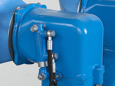
Drive shaft
Useful information about the drive shaft
The drive shaft or cardan shaft generally consists of two U-joints. It facilitates the transfer of torque through a flexed shaft train. In the case of a severe flex, such as with trailing sprayers, a double joint (wide angle) is used on the device side to counteract the extreme angle.
In the case of a full 80° steering lock, it is recommended to always briefly uncouple the shaft to reduce wear to the double joint!
- Ensure that the drive shaft has a distance of at least 20cm on trailers and at least 6cm on attachments from the plunge (note when changing the tractor).
- Regularly check the sectional tubes for friction. Take apart the shaft and carefully check there are no sharp edges on the inner pipe (risk of cutting). Warning: Don’t be misled when checking the anti-friction finish!
- Regularly lubricate the joints and sectional tubes despite their teflon coating.
farmunited
All you need to know about CleverSpray
CleverSpray from farunited is a high-precision measurement and regulation system that offers controlled, efficient and replicable crop protection. CleverSpray can be controlled via your smartphone or tablet. The app uses GPS to identify the piece of land in question and selects the corresponding spray programme. The pesticide is automatically dosed based on the area and the vehicle speed. This precise dosing saves pesticide and money. Wireless web access means that you can share data and management of the spray programmes, job and machine data. CleverSpray is simple and intuitive to use and can be retrofitted to almost any existing machine. Automatic updates keep the app up-to-date at all times.
Videos
- Cloud - Initial steps
- Cloud - Register and login
- Cloud - Create spray programme
- Cloud - Add pesticides
- Cloud - Create job
- Cloud - Add driver
- Cloud - Connect tablet with Cloud and machine
- Cloud - Set up backups
- Cloud - Software update
- Cloud - Update data from Cloud
- CleverSpray - Activate automated section control (SSC)
- CleverSpray - Recording (Start / Stop / Pause)
- CleverSpray - Emergency operation
- CleverSpray - Manual operation (constant pressure) with “Easy Limit”
- CleverSpray - Pressure-based automatic mode (consistent output)
- CleverSpray - Flow-based automatic mode (consistent output)
- CleverSpray - Job mode (fully automatic)
Cleaning
Useful information about cleaning and maintenance
Please be aware that you should never use strong detergents or high-pressure cleaners when cleaning a VICAR sprayer. This will help to avoid damage to electronic components, such as motors and sensors, as well as to glass-fibre and cast aluminium parts.
Otherwise, the solvents contained in the detergent will attack the different materials within the plastic coating, including thermoplastics, thermosetting plastics and elastomers. Using high-pressure cleaners can make the GRP composite soft and unstable. For cast parts, the coating can become eroded in vulnerable places (e.g. scratches) and will gradually peel away. As such, any damaged areas should be sealed with spray paint.
Tip: Spray the machine with penetrating oil or wax prior to initial use to prevent the pesticide from sticking. Afterwards, simply rinse with the domestic water supply and gently sponge clean if required. This sealant is easy to maintain and offers additional corrosion protection.